Induced current in electrodes
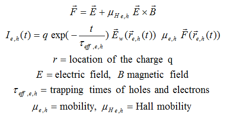
There are several excelent books and papers describing the singal formation in any detector (look for paper from S. Ramo and further works of Gatti, Mafredi, H. Spieler, V. Radeka). The PhD thesis of G. Kramberger which is the basis for this work deals in details particularly for signal formation in radiation damaged detectors.The current induced by the motion of the carriers (electrons-e, holes-h) in the electric field induces current in the electrodes connected to low impedance as given by equation
In order to simulated the induced current in the detector the knowledged of electric field and weigthing field in the detector is crucial. It is always assumed that magnetic field in the sensors is constant.
Calculation of electric field
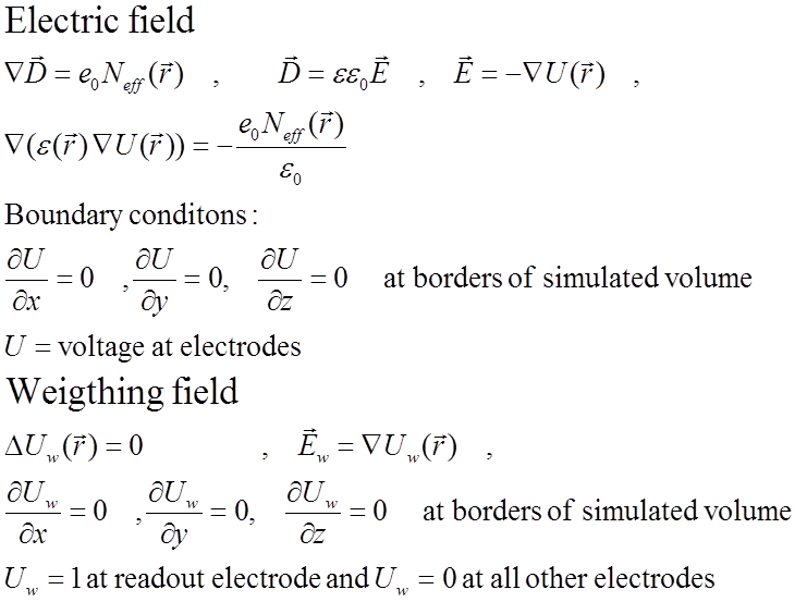
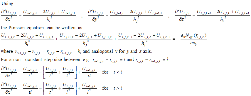
In the KDetSim it is assumed that the device is in steady state. That means that free carrier concentrations do not change in time, but remain constant. By that one avoids solving a standard set of semiconductor eqautions (see Zse), which adds to the complexity. The free carriers generated by the ionizing particle should therefore present a negligible dynamic disturbance of the electric field (huge ionization produced by heavy ions for example can not be properly simulated). The generated e-h pairs are considered to be moving in quasi-static electric field.Both electric field and weigthing field can be calculated from
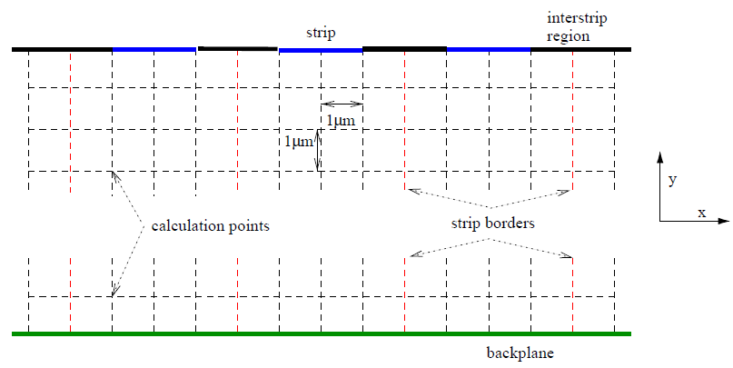
The partial differential equation is solved numericaly by using finite difference equation on the mesh (FEM approach). An example of the mesh in 2D is shown in figure below. The mesh can be defined in 3D with complex electrode arrangements/shapes (see examples). The mesh should be ortoghonal but doesn't have to be equidistant.
The differnial equation translates to solving the system of equations for U, where every node represents an equation. The boundary conditions are esential as they determine the solution of the equatuions. The system of equations is solved by inverting the matrix (see KDetector for software details). When simulating a 3D structure (Pixel detector) the system results in large number of equations (Nx*Ny*Nz). The matrix which should be inverted is sparse which significantly speeds up its inverse, so 1e6 node system is solved in the time scale of minutes on Sandybridge Core I7 portable CPU .
Simulaton of the drift
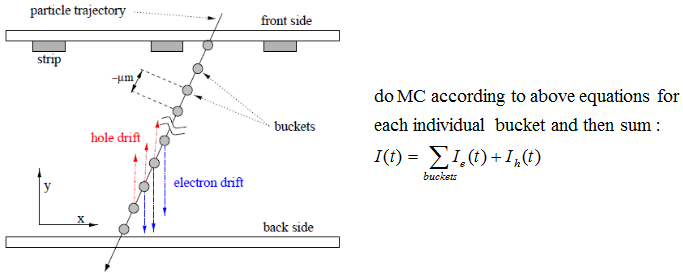
Any non-equilibrium free carrier distribution (e-h pairs) due to traversing minimum ionizing particle, laser light, alpha particle, photoelectic effect etc., is divided into charge buckets. Each bucket is considered as a point charge (with given number of e-h pairs) which is transported in the electric and magnetic field according to the Lorentz force and diffusion.
 The transport is done in steps defined by the user, where step size is defined by the user. For each step drift and diffusion components are summed and corresponding induced charge, drift time, charge from impact ionization etc. are calculated.
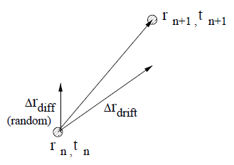 The charge transport is finished when, charge reaches the electrodes or boundaries of the simulated volume.
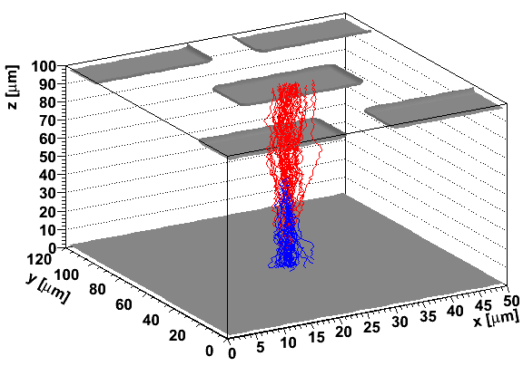
An example of the e-h pairs drift after mip particle
traversing pixel detector perpendicularly is shown in figure below (blue electron, red holes).
The charge transport is finished when, charge reaches the electrodes or boundaries of the simulated volume.
An example of the e-h pairs drift after mip particle
traversing pixel detector perpendicularly is shown in figure below (blue electron, red holes).