User guide
The purpose of the library is twofold. On one side it is meant to be used for solution of Poisson/Laplace equation for any geometry in 2D or 3D and on the other to simulate charge transport in such a detector structure. Although there are several commercial packages available on the market they are not suited for fast simulation of semiconductor detectors, as they are far more orineted to simulation of electronics.
The main input to the solver is space charge distribution, which is used to calculate the electric field. Unlike the commercial packages KDetSim is therefore not intended to be used for calculatation of electric field from the from the defects' parameters nor explain the leakage current and trapping behaviour. These are all inputs to the KDetSim and should be derived from the measurements. As is focuses to the simulation of charge collection it is well suited for multi-electrode problems through the concept of so called weigthing field (a.k.a Ramo field).
The difference between the powerfull comercial software like Synopsis-TCAD and the KDetSim is mainly in the following:
- it is fast and allows iterative approaches - minimization of multi-parameter problems
- allows Monte-Carlo simulatation of the transport of the generated charge instead looking at free carrier concentration relaxation
- allows expanding of simulated structures over larger volume and by that e.g. effects related to multi-electrode readout like charge sharing
- it is easly incorporated in any C++/ROOT/GEANT4 based physics generator
Induced current in electrodes
There are several excelent books and papers describing the singal formation in any detector (). The current induced by the motion of the carriers (electrons-e, holes-h) in the electric field induces current in the electrodes connected to low impedance as given by equation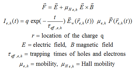
In order to simulated the induced current in the detector the knowledged of electric field and weigthing field in the detector is crucial. It is always assumed that magnetic field in the sensors is constant.
Calculation of electric field
Electric field and weigthing field is calculated as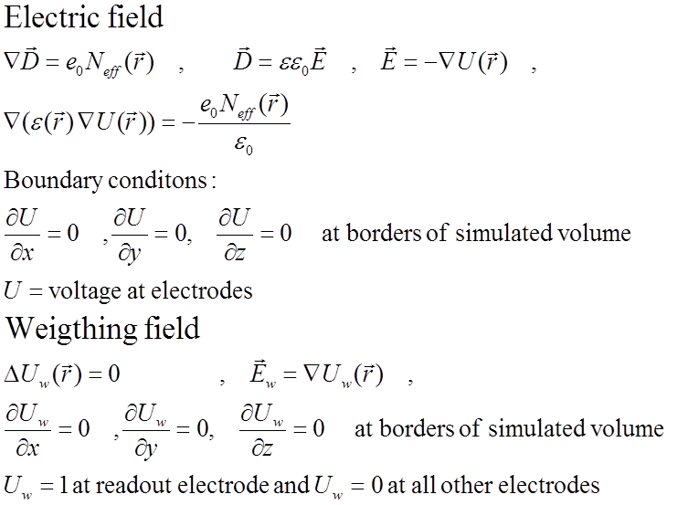
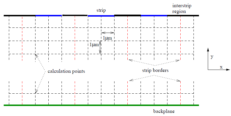
The partial differential equation is solved numericaly by using finite difference equation on the mesh. An example of the mesh in 2D is shown in figure below. The mesh can be defined in 3D with complex electrode arrangements/shapes (see examples). The mesh should be ortoghonal but doesn't have to be equidistant.
Simulaton of the drift
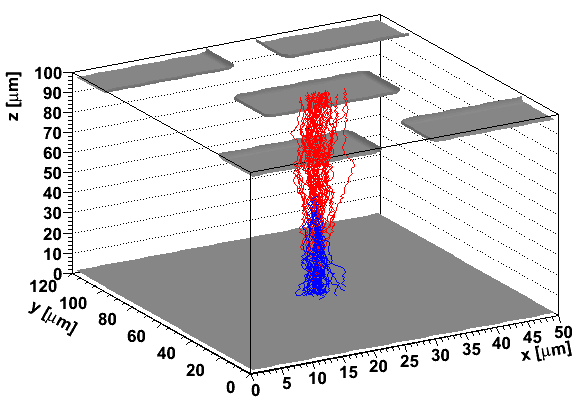
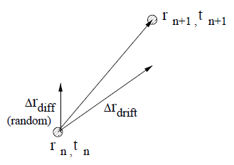
In order to simulate induced current any charge distribution, either due to mip particle, alpha or laser generation is devided into charge buckets. Each bucket is considered as a point charge (with given number of e-h pairs) which is transported in the electric and magnetic field taking into account also diffusion.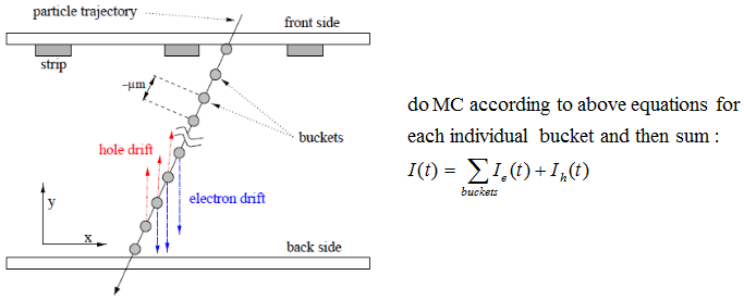 This is done in steps, where step size is defined by the user. For each step drift and diffusion components are summed and corresponding induced charge, drift time, charge from impact ionization etc. are calculated. The charge transport is finished when, charge reaches the electrodes or boundaries of the simulated volume.
 An example of the e-h pairs drift after mip particle
traversing pixel detector perpendicularly is shown in figure below (blue electron, red holes).
An example of the e-h pairs drift after mip particle
traversing pixel detector perpendicularly is shown in figure below (blue electron, red holes).