Checking BGO blocks
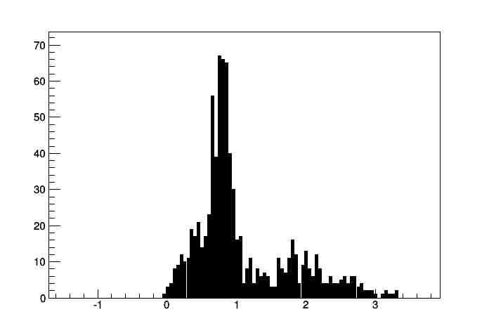
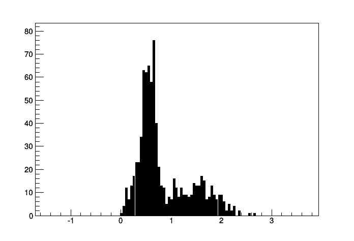
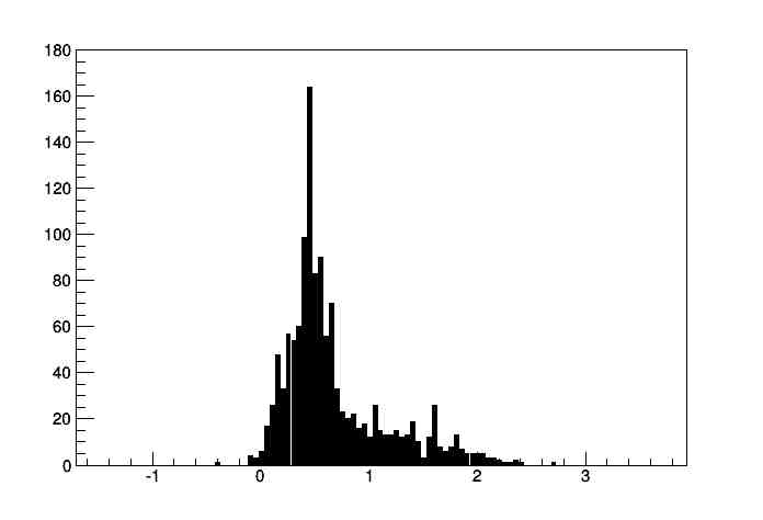
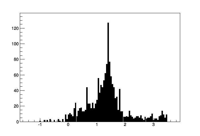
Connected 4 channels to LeCroy WaveRunner 6200 A, use LL as the trigger, sum of 4 channels. Histogram Level@X on the SUM(F3), store histograms. The following is the table of pairs of PMT blocks and associated spectra stored on the scope.
PMT R01 F4spectrum00003.txt
PMT R02 F4spectrum00004.txt
PMT R03 F4spectrum00006.txt
PMT R04 F4spectrum00015.txt
PMT R05 F4spectrum00014.txt
PMT R06 F4spectrum00007.txt
PMT R07 F4spectrum00008.txt
PMT R08 F4spectrum00009.txt
PMT R09 F4spectrum00010.txt
PMT R10 F4spectrum00011.txt
PMT R11 F4spectrum00012.txt
PMT R12 F4spectrum00013.txt
PMT L01 F4spectrum00016.txt
PMT L02 F4spectrum00017.txt
PMT L03 F4spectrum00019.txt
PMT L04 F4spectrum00020.txt
PMT L05 F4spectrum00021.txt
PMT L06 F4spectrum00022.txt
PMT L07 F4spectrum00001.txt
PMT L08 F4spectrum00023.txt
PMT L09 F4spectrum00024.txt
PMT L10 F4spectrum00025.txt
PMT L11 F4spectrum00026.txt
PMT L12 F4spectrum00002.txt
We changed threshold on L08 and L09 from -30 to -100 mV.
Map of modules
This is how the modules are connected:
00  R01 R11 R12
04  R03 R02 R10
08  R04 R07 R09
12  R05 R06 R08
16  L09 L05 L01
20  L10 L06 L02
24  L11 L07 L03
28  L12 L08 L04
The left column goes to the leftmost ADC module with address acac, mapped as 300, the middle to the rightmost, address acae, mapped as 302 and the right column goes to the middle ADC module, address acad, mapped as 301.
Triggers come in like this:
00  reserved for Si
01  reserved for Si
02  L01
03  L02
04  L03
05  L04
06  L05
07  L06
08  L07
09  L08
10  L09
11  L10
12  L11
13  L12
14  empty
15  empty
16  reserved for Si
17  reserved for Si
18  R01
19  R02
20  R03
21  R04
22  R09
23  R10
24  R11
25  R12
26  R05
27  R06
28  R07
29  R08
30  empty
31  empty
Rates observed on the blocks
Tested with ORTEC 994 counter and NIM to TTL converters in the NIM bin. Each LL trigger was connected to NIM to TTL and plugged to IN B, time was set to 0.01 scale and PRESET was set to 012, meaning 1 times 10 to the power of 2. The following modifications were made. The source was 30 uCi at Sep 1 2006, equivalent to 10 kBq today. Expected counts from source are 250 Hz per block.
- L1 from 43 to 75, cold rate 434 -> 262, hot rate 800->600
- L2: 152 to 62; 20->260; X->750
- L4: 40 to 80; 300->150; 800->480
- L7: 44 to 71 to 80; 500->400->250; 2000->730->480
- L8: 101 to 148; 1500->226; X->415
- L9: 84 to 162; 5000->264; X->400
- L10: 70 to 43; 80->150; 350->500
- R1: 78 to 98; 320->220; 700->500
- R2: 20 to 38; 330->110; 985->550
- R5: 109 to 141; 1800->400; X->550
- R9: 61 to 87; 400->160; 720->450
The final threshold (THR) /rate cold (CLD) /hot (HOT) /average gain (GAI) follows
PMT THR CLD HOT GAI
L01 075 260 600 1.1
L02 152 260 750 0.6
L03 022 220 730 0.7
L04 080 150 480 1.1
L05 046 250 740 1.5
L06 035 140 550 0.9
L07 080 250 480 0.6
L08 148 230 415 0.9
L09 162 260 400 0.8
L10 043 150 500 0.7
L11 050 190 560 0.7
L12 046 190 550 0.6
R01 098 220 550 1.1
R02 038 110 580 0.5
R03 075 200 520 1.1
R04 072 220 600 0.8
R05 141 400 480 0.5
R06 073 120 440 0.8
R07 049 090 460 tp
R08 087 180 390 0.9
R09 087 160 450 0.9
R10 051 180 560 0.6
R11 051 120 550 0.5
R12 045 180 620 1.5
Apllying criteria HOT/COLD > 2.5 and GAIN >= 0.7 for excellent, and HOT/COLD<2 and GAIN <= 0.7 for BAD, the following groups were made:
EXCELLENT: L03 L04 L05 L06 L10 L11 R01 R03 R04 R06
___OK___ : L01 L02 L08 R02 R07 R08 R10 R11
__BAD___ : L07 L09 L12 R05
To get the excellent ones on the inside, the following swaps have to be made:
- R01 and R05
- L01 to L03; L03 to L07; L07 to L01
- L09 and R12
- L08 and L10
- R03 and R07
- L11 and R08
- L12 and R12 (see below)
- R07 and L07 (same reason)
The final layout will be:
R07     R05
L02     R02
L01     L07
L04     R04
L05     R01
L06     R06
L03     R03
L10     L11
L12     R09
L08     R10
R08     R11
R12     L09
Changed all widths of LL (or UL, in two cases) to 100 ns. Then had to change threshold of another 8 pmts (see below). This is what I ended up with:
L01 R07 037 120 0700    missing CH2
L02 L02 027 500 1400    070 100 600
L03 L01 076 230 0850
L04 L04 079 150 0650
L05 L05 047 300 1000    099 100 570
L06 L06 083 150 0600
L07 L03 022 280 1200    044 120 650
L08 L10 045 160 0800
L09 L12 046 240 0800
L10 L08 145 200 0450    UL
L11 R08 085 260 0700
L12 R12 043 300 1200    116 180 580 missing CH2
R01 R05 141 440 0400    UL
R02 R02 038 180 0800
R03 L07 080 160 0500
R04 R04 072 350 0900    102 150 600
R05 R01 098 200 0800
R06 R06 075 134 0560
R07 R03 075 370 1000    128 150 600
R08 L11 048 400 0900    063 250 700
R09 R09 087 220 0550
R10 R10 054 200 0800
R11 R11 052 200 0800
R12 L09 163 020 0050    044 136 220 missing CH1
Maybe unfortunate choice of R08.
After flood, PMT L09 (R12 originally) has PMT on CH2 not working. To compensate, replacing L12 and L09. This means that L12 is where R12 is sitting, and at L09 we will have L12.
Also, current R03, originally R07, has PMT 2 not working. Moving it out of the way on L01, where L07 is sitting. Hence the second move.
Troubles reading out R03 (block 14) and R10 (block 21). Replacing the electronic box. Redoing the flood (20150902). This is supposed to be the final arrangement.