Process si calibration run
Parse the data using observer and decoderSiSparse. Typical
configuration file processSi257.config looks like this:
#run with decoderSiSparse
files=/storage/data/20161206/si/Am241_si257_thr180_adj3_
eventsDotOut=/storage/data/20161206/si/out/Am241_si257_thr180_adj3.out
nPedestal=10000
configFile=/storage/data/imageRec/layout/setupOSU/setup257.in
The configuration file setup257.in has for all modules but module
257 flag on set to 0. Part of setup257.in is the calibration file of
module 257:
layout_0=layoutSi.in
parseSettings_0=parseSettings.in
calib_0=calib257.in
output_0=output.in
Setup files layoutSi.in, parseSettings.in and output.in are generic. The layout file needs a channel layout map, for 1040 detector this is d770g_1040padMap.txt.
The calibration file calib257.in looks like this:
path=/storage/data/imageRec/studies/setup_osu
gain=unitGain_sintef512.out
#gain=gainADC_257_20161206.out
gainFitFile=gainFitPol5_20090615_avg_gp7.out
fitMode=AVGPOL5
mask=mask257.txt
The non-linearity of GP7 is compensated by gainFitPol5_20090615_avg_gp7.out, and mask257.txt reflects the masked channels used in data collection.
For the first pass, use unitGain_sintef512.txt and comment out any specific gain files. Do the actual processing:
cd software/build/observer
make
make decoderSiSparse
bin/decoderSiSparse
/storage/data/imageRec/studies/setup_osu/processSi257.config
Determine gain correction factors in ROOT:
cd software/build/observer_tools/parse_si/root_scripts
root
processData pd
processSettings ps
ps.iModule=257
ps.mode=4
processGainAm("/storage/data/20161206/si/out/Am241_si257_thr180_adj3_g1_s0_s0.out",pd,ps)
dumpGain(pd,"/storage/data/imageRec/studies/setup_osu","257_20161206")
Change gain settings in calib257.in:
#gain=unitGain_sintef512.out
gain=gainADC_257_20161206.out
Reprocess
rm /storage/data/20161206/si/out/Am241_si257_thr180_adj3_g*
bin/decoderSiSparse
/storage/data/imageRec/studies/setup_osu/processSi257.config
Plot the resulting spectrum in root
cd software/build/observer_tools/parse_si/root_scripts
root
TTree*t=
makeTree("/storage/data/20161206/si/out/Am241_si257_thr180_adj3_g1_s0_s0.out")
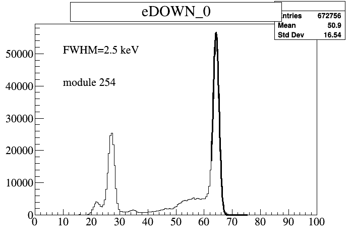
t->Draw("eDOWN_0>>(200,0,100)")
c1->Print("/storage/data/imageRec/studies/setup_osu/Am241_254_spectrum.root")
c1->Print("/storage/data/imageRec/studies/setup_osu/Am241_254_spectrum.png")
You can also fit the photopeak, which is indicative of the silicon performance.
Process BGO calibration run
Login to hrpet1. Do the BGO run via
./scripts/run_bgo_flood.sh
Login to hrpet2 for analysis. List possible data files:
./scripts/list_hrpet1.sh
./scripts/copy_hrpet1.sh date
The copy should give you the run directories also.
For the processing, do:
~/scripts/run_flood_analysis.sh date run,
where run is 0,1 or whatever the run number is, but not run0, which is the name of the actual directory.
Then, create a new calibration data point by running:
~/scripts/insert_calibBGO_data.sh [date] [run]
Date and run are parameters of the flood run. There should be a new calibration
directory created under ${IMAGE_REC}/calibBGO with the date of the
run.
[UPDATE: Not required any longer, performed by insert_calibBGO_data].
To extract positioning information, the setup configuration file needs to be updated. To do that:
cd /data/imageRec/studies/setup_osu
vi env.sh
# correct BGO_CALIBRATION_DATE to the new calibration date
./make_config config/setupBGO.template.in [whateverDate] [whateverRun]
Then start root from the flood directory:
cd /software/build/observer_tools/flood/root_scripts
root
root[] mesh_optimizer m;
#get the configuration
root[] m.parse("/data/imageRec/studies/setup_osu/config/setupBGO.in",0)
#we use 0 because BGO is the first module
root[] m.initData(300);
#normally 300 works, but if you get few entries, try 301 also
Then, go module by module by doing:
root[] m.initMesh(1);
root[] m.h2.GetListOfFunctions()->RemoveAt(1)
root[] m.drawCenters(kGreen);
The command initMesh tries to segment the Anger maps to find centers of 32 PMTs. The second command draws the Anger map with overlaid centers. You can correct the centers found by moving them around with a mouse. If the centers are a big mess, dump them, correct the file and reload them:
root[] m.saveCenters("temp.out")
root[] m.readCenters("temp.out")
A defaultCenterMap.txt has approximate positions of the centers, and can also be used.
After the centers seem at an appropriate place, run
root[] m.setCentersFromImage();
to copy position of markers to actual center data. After that, create a mesh, that is division between blocks, map it to a histogram and store it.
root[] m.makeMesh();
#this is for QA
root[] m.drawMesh(kGreen);
#do this only once
root[] TH2D hd;
root[] m.drawHisto(hd);
#saves current block only, uses file name from configuration file
root[] m.saveHisto(hd);
If the procedure fails and data is bad, don't perform drawHisto and saveHisto steps; by default, the values are set to avgMesh.txt.
skip the block and keep avgMesh.txt as the mesh file for the block.
The processing file looks like this:
#run with bin/decoderBgoFlood
files=/storage/data/20161206/flood/Na22_flood
eventsDotOut=/storage/data/20161206/flood/out/Na22_flood.out
nPedestalBGO=1000
configFile=/storage/data/imageRec/layout/setupOSU/setupBGO.in
The setup file setupBGO.in is the master configuration file. These are the important lines:
fpga_id=100
#id
#
#
setupID=0
#
#
#modules
#
#
nModules=1
#
#next module, bgo
#
type_0=3
setupPath_0=/storage/data/imageRec/layout/setupOSU
studyPath_0=/storage/data/imageRec/studies/setup_osu
geo_0=_setupPath_/ringUm.in
channels_0=_setupPath_/chOSU.in
settings_0=_setupPath_/settings.in
arcs_0=_setupPath_/arcsOSU.in
adcs_0=_setupPath_/adcsOSU.in
blocks_0=_setupPath_/blocksOSU.in
blockCalib_0=_studyPath_/blockCalib_20161206.in
The geo are the geometrical parameters of the block detector:
nCrystalPerModule=32
nModulesPerCircle=64
nCrystalPerRowInModule=8
crystalSizeY=13.35
The channels gives layout of the electronic channels. Each channel is connected to an ADC module at a certain channel number, but is also part of a particular block at a particular relative position within that block. Information on all these parts is given in the channels map, with a typicall channel looking like this:
block_3=12
relPos_3=3
adc_3=300
adcCh_3=3
That means that channel, refered to as the third in the internal channel numbering, is part of block 12, at a relative position of 3, connected to ADC with id=300 as the third channel in that module.
The settings file gives information on the processing strategy:
noise_cut=5
block_effect=1.5
Noise cut is the level (in baseline RMS variation) above which signal is considered significant. Block effect is the combined effect of crystal misidentification and multi-scattering events, smearing the resolution of the scanner. This is used in reconstruction.
The arcs file gives information on arcs:
nArcs=2
#
#
#specify id and position/rotation
arcID_0=300
ID_0=300
pos_x_0=0
pos_y_0=0
pos_z_0=0
rot_xx_0=-1
rot_xy_0=0
rot_xz_0=0
rot_yx_0=0
rot_yy_0=-1
rot_yz_0=0
rot_zx_0=0
rot_zy_0=0
rot_zz_0=1
rho_0=520
side_0=0
sideID_0=10
#
#repeat this for second block
Each arc has an ID (repeated twice for different parts of the program), a position and a rotation, side and side identifier and the arc radius.
The adcs just lists the ADC modules used.
The blocks file contains list of blocks, their relative position in arcs and channels in the trigger register. An example:
relPos_0=0
trigCh_0=2
arc_0=300
Block with (an arbitrary sequential) number 0 is at relative position 0 in arc 300, and the trigger goes to position 2 in the trigger register of the FPGA.
The calibration part of the blocks is in a separate blockCalib file. Each block has a mesh histogram, between a bit less than 0 to a bit more than 128 with arbitrary binning, representing a map from Anger derived position between 0 and 128 in each direction and a particular crystal ID, coded as the content of the histogram. Additionaly, a gain maps the sum of 4 channels (in ADC) to energy for a particular block:
block_0=0
mesh_0=avgMesh.txt
gain_0=GainOfOne.txt
#gain_0=GainOfOne.txt
General data specify the mesh histogram layout, the flood file and path used in calibration and number of blocks:
nBlocks=24
calibPath=/storage/data/20161206/flood/out
calibFile=Na22_flood_B1_V1_s0_s0.out
xmin=-10
xmax=138
ymin=-10
ymax=138
xnbins=100
ynbins=100
#
Run the processing routine with mesh set to avgMesh.txt and gain to GainOfOne.txt.
cd software/build/observer
make decoderBgoFlood
bin/decoderBgoFlood /storage/data/imageRec/studies/processFlood.config
Change mesh files to desired names. Go to root:
cd software/build/observer_tools/flood/root_scripts
root
root[] mesh_optimizer m;
#get the configuration
root[] m.parse("/storage/data/imageRec/layout/setupOSU/setupBGO.in",0)
#we use 0 because BGO is the first module
We have to peak which module was used to derive variable names. We do
that by looking at file generated by decoderBgoFlood, set by
eventsDotOut variable in the configuration file with added
B1_V1_s0_s0:
>head /storage/data/20161206/flood/out/Na22_flood_B1_V1_s0_s0.out
#ie  FPGAid evt_time coinc trig_reg ch0 time0  adc300ID hitBlock300
sig300_0 sig300_1 sig300_2 sig300_3 hitCrystal300 e300   status
0  11110100 c4cae8ca98b 1000 0 9 -52  11110300  7 30.1116 -0.945148
0.204348 0.0124481 224 33.8739  22000000
We are looking for the number next to hitBlock and other names in the first, commented line of the file. It turns out to be 300, which we use in the next root command:
root[] m.initData(300)
nEntries=16/16
ie:FPGAid:evt_time:coinc:trig_reg:ch0:time0:adc300ID:hitBlock300:sig300_0:sig300_1:sig300_2:sig300_3:hitCrystal300:e300:status
nVar=16
nLines=838305
ADDENDUM:
The 20120518 flood files were actually made in coinc mode. So we have both 300
and 301 blocks in the file. Start by m.initData(300) and set modules 0 through 11.
First one should transliterate the module numbers from the 2012's scheme to recent scheme
by running:
cd /afs/f9.ijs.si/data/lab/studen/processed_data/20120518/flood/out
./transliterate.awk Na22_1040_20120518_BGO_B2_V2_s0_s0.out > Na22_1040_20120518_BGO_B2_V2_s0_s0_transliterated.out
sed -i.bu '/^#/{s% 0 % hitBlock300 %; s% 12 % hitBlock301 %;}' Na22_1040_20120518_BGO_B2_V2_s0_s0_transliterated.out
and correct calibFile in the blockCalib file.
END ADDENDUM
Now we go, block by block, doing the following. First initialize the mesh for the block:
root[] m.initMesh(1);
root[] m.h2.GetListOfFunctions()->RemoveAt(1)
root[] m.drawCenters(kGreen);
The command initMesh tries to segment the Anger maps to find centers of 32 PMTs. The second command draws the Anger map with overlaid centers. You can correct the centers found by moving them around with a mouse. If the centers are a big mess, dump them, correct the file and reload them:
root[] m.saveCenters("temp.out")
root[] m.readCenters("temp.out")
A defaultCenterMap.txt has approximate positions of the centers, and can also be used.
After the centers seem at an appropriate place, run
root[] m.setCentersFromImage();
to copy position of markers to actual center data. After that, create a mesh, that is division between blocks, map it to a histogram and store it.
root[] m.makeMesh();
#this is for QA
root[] m.drawMesh(kGreen);
#do this only once
root[] TH2D hd;
root[] m.drawHisto(hd);
#saves current block only, uses file name from configuration file
root[] m.saveHisto(hd);
If the procedure fails and data is bad, skip the block and keep avgMesh.txt as the mesh file for the block.
Exit root.
Rerun decoderBgoFlood, remember, we are using the mesh information to split data to crytals. Keep gains set to GainOfOne.txt
rm /storage/data/20161206/flood/out/Na22*
cd software/build/observer
make decoderBgoFlood
bin/decoderBgoFlood /storage/data/imageRec/studies/processFlood.config
Now, change gains to desired names. Run root, start mesh optimizer, process the data to get gains and store them.
cd software/build/observer_tools/flood/root_scripts
root
root[] mesh_optimizer m;
root[] m.parse("/storage/data/imageRec/layout/setupOSU/setupBGO.in",0);
root[] TH1D h1;
root[] m.getGain(h1);
# uses files from calibBlock configuration files
root[] m.writeGain(h1);
Now, rerun with the gains set:
rm /storage/data/20161206/flood/out/Na22*
cd software/build/observer
make decoderBgoFlood
bin/decoderBgoFlood /storage/data/imageRec/studies/processFlood.config
In root, load tree:
root[] TTree *t =
makeTree("/storage/data/20161206/flood/out/Na22_flood_B1_V1_s0_s0.out");
root[] t->Draw("e300>>(1000,0,2000)");
The last command gives a spectrum, which should be sufficiently narrow (around 20 % or so FWHM), indicative of success of proper Anger formula mapping and gain calibration.
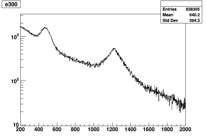
Efficiency
The long way and the short way. The short way first.
Make sure the corresponding coincFlag entries in study file have fields dataImport, sinoMatrix and forwardMatrix set to something sensible. Then do:
root[] DataReader r
root[] r.ImportStudy("/data0/studen/data/imageRec/studies/setup_um/setup_um_study.in")
root[] TMatrixD m,f;
#the following store the matrices
root[] r.generateCrystalMatrix(m,0x100)
root[] r.estimateCrystalMatrix(f,0x100);
#write corrections to corresponding files
root[] r.setEfficiency(0x100);
More intermediate step in the longer version below.
root[] DataReader r
root[] r.ImportStudy("/data0/studen/data/imageRec/studies/setup_um/setup_um_study.in")
root[] TMatrixD m,f;
root[] r.generateCrystalMatrix(m,0x100)
root[] r.estimateCrystalMatrix(f,0x100);
root[] double scale,bkg;
root[] fit(f,m,scale,bkg);
root[] TMatrixD pc(m);
root[] TMatrixD q=scale*f+bkg;
root[] ElementDiv(pc,q);
#now to PCA
root[] TDecompSVD svd(pc);
root[] svd.Decompose();
#power of first solution
root[] svd.GetSig()(0)*svd.GetSig()(0)/svd.GetSig().Norm2Sqr();
#i-s are 300, j-s are 301, i-s are related to U, j-s to V
root[] TMatrixD fu(svd.GetU())
root[] TMatrixD fv(svd.GetV())
root[] TVectorD eff300(TMatrixDColumn(fu,0));
root[] TVectorD eff301(TMatrixDColumn(fv,0));
#check results
root[] TMatrixD eff(eff300.GetNoElements(),eff301.GetNoElements())
root[] for (int i=0;i<eff.GetNrows();i++) { for (int j=0;j<eff.GetNcols();j++) { eff(i,j)=eff300(i)*eff301(j);}}
Process LYSO calibration
Run:
$>~./scripts/pet/insert_calibLYSO_data.sh 20180406 1
Use flood/root_scripts, do
root[] mesh_optimizer m
root[] m.parse("/storage/data/imageRec/studies/setup_osu/config/setupLYSO.in",0);
root[] m.initData(500)
root[] m.initMesh(0)
root[] m.addSlice(30,10)
root[] m.drawSlice(0)
#adjust center markers
root[] m.addSlice(65,20)
root[] m.drawSlice(1)
#adjust center markers
root[] m.addSlice(90,20)
root[] m.drawSlice(2)
#adjust center markers
root[] m.drawMarkers(kGreen)
#admire work, adjust top and bottom graphs to match data extension
root[] m.setCentersFromSlices()
root[] m.makeMesh()
root[] m.drawMesh(kGreen)
#admire work, correct if neccessary
root[] TH2D h2;
root[] m.drawHisto(h2)
#takes a while
root[] m.saveHisto(h2)
Make sure you change the LYSO calibration data in /storage/data/imageRec/studies/setup_osu/env.sh